قوة محركة كهربائية
| كهرومغناطيسية | ||||||||||

| ||||||||||
كهرباء • مغناطيسية
| ||||||||||
القوة المحركة الكهربائية (قم) هي الطاقة اللازمة لتحريك الإلكترونات المكونة للتيار أو بمعنى آخر هي الطاقة التي يعطيها المولد لكل كولوم يجتازه. و القوة المحركة ليست قوة ميكانيكية ولكنها طاقة وحدة الشحنات ووحدة قياسها هي ذاتها وحدة قياس فرق الجهد والفرق بينهما هو أن القوة المحركة تمثل الطاقة المكتسبة أما فرق الجهد بن نقطتين فهو يمثل الطاقة المفقودة.
. . . . . . . . . . . . . . . . . . . . . . . . . . . . . . . . . . . . . . . . . . . . . . . . . . . . . . . . . . . . . . . . . . . . . . . . . . . . . . . . . . . . . . . . . . . . . . . . . . . . . . . . . . . . . . . . . . . . . . . . . . . . . . . . . . . . . . . . . . . . . . . . . . . . . . . . . . . . . . . . . . . . . . . .
التوليد
المصادر الكيميائية

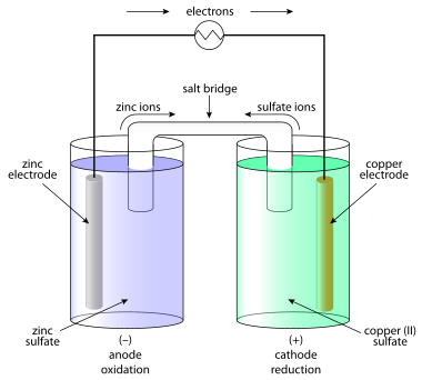
The question of how batteries (galvanic cells) generate an emf occupied scientists for most of the 19th century. The "seat of the electromotive force" was eventually determined in 1889 by Walther Nernst[2] to be primarily at the interfaces between the electrodes and the electrolyte.[3]
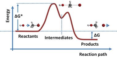
Atoms in molecules or solids are held together by chemical bonding, which stabilizes the molecule or solid (i.e. reduces its energy). When molecules or solids of relatively high energy are brought together, a spontaneous chemical reaction can occur that rearranges the bonding and reduces the (free) energy of the system.[4] خطأ استشهاد: إغلاق </ref> مفقود لوسم <ref> Volta correctly identified the role of dissimilar electrodes in producing the voltage, but incorrectly dismissed any role for the electrolyte.[5] Volta ordered the metals in a 'tension series', “that is to say in an order such that any one in the list becomes positive when in contact with any one that succeeds, but negative by contact with any one that precedes it.”[6] A typical symbolic convention in a schematic of this circuit ( –||– ) would have a long electrode 1 and a short electrode 2, to indicate that electrode 1 dominates. Volta's law about opposing electrode emfs implies that, given ten electrodes (for example, zinc and nine other materials), 45 unique combinations of voltaic cells (10 × 9/2) can be created.
القيم النمطية
The electromotive force produced by primary (single-use) and secondary (rechargeable) cells is usually of the order of a few volts. The figures quoted below are nominal, because emf varies according to the size of the load and the state of exhaustion of the cell.
| EMF | Cell chemistry | Common name | ||
|---|---|---|---|---|
| Anode | Solvent, electrolyte | Cathode | ||
| 1.2 V | Cadmium | Water, potassium hydroxide | NiO(OH) | nickel-cadmium |
| 1.2 V | Mischmetal (hydrogen absorbing) | Water, potassium hydroxide | Nickel | nickel–metal hydride |
| 1.5 V | Zinc | Water, ammonium or zinc chloride | Carbon, manganese dioxide | Zinc carbon |
| 2.1 V | Lead | Water, sulfuric acid | Lead dioxide | Lead–acid |
| 3.6 V to 3.7 V | Graphite | Organic solvent, Li salts | LiCoO2 | Lithium-ion |
| 1.35 V | Zinc | Water, sodium or potassium hydroxide | HgO | خلية الزئبق |
الخلية الشمسية

Operation of a solar cell can be understood from the equivalent circuit at right. Light, of sufficient energy (greater than the bandgap of the material), creates mobile electron–hole pairs in a semiconductor. Charge separation occurs because of a pre-existing electric field associated with the p-n junction in thermal equilibrium. (This electric field is created from a built-in potential, which arises from the contact potential between the two different materials in the junction.) The charge separation between positive holes and negative electrons across a p-n junction (a diode) yields a forward voltage, the photo voltage, between the illuminated diode terminals,[8] which drives current through any attached load. Photo voltage is sometimes referred to as the photo emf, distinguishing between the effect and the cause.
The current available to the external circuit is limited by internal losses I0=ISH + I D:
Losses limit the current available to the external circuit. The light-induced charge separation eventually creates a current (called a forward current) ISH through the cell's junction in the direction opposite that the light is driving the current. In addition, the induced voltage tends to forward bias the junction. At high enough levels, this forward bias of the junction will cause a forward current, I D in the diode opposite that induced by the light. Consequently, the greatest current is obtained under short-circuit conditions, and is denoted as IL (for light-induced current) in the equivalent circuit.[9] Approximately, this same current is obtained for forward voltages up to the point where the diode conduction becomes significant.
The current delivered by the illuminated diode, to the external circuit is:
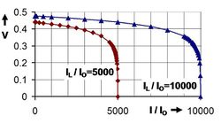
where I0 is the reverse saturation current. Where the two parameters that depend on the solar cell construction and to some degree upon the voltage itself are m, the ideality factor, and kT/q the thermal voltage (about 0.026 V at room temperature).[9] This relation is plotted in the figure using a fixed value m = 2.[10] Under open-circuit conditions (that is, as I = 0), the open-circuit voltage is the voltage at which forward bias of the junction is enough that the forward current completely balances the photocurrent. Solving the above for the voltage V and designating it the open-circuit voltage of the I–V equation as:
which is useful in indicating a logarithmic dependence of Voc upon the light-induced current. Typically, the open-circuit voltage is not more than about 0.5 V.[11]
When driving a load, the photo voltage is variable. As shown in the figure, for a load resistance RL, the cell develops a voltage that is between the short-circuit value V = 0, I = IL and the open-circuit value Voc, I = 0, a value given by Ohm's law V = I RL, where the current I is the difference between the short-circuit current and current due to forward bias of the junction, as indicated by the equivalent circuit[12] (neglecting the parasitic resistances).[13]
In contrast to the battery, at current levels delivered to the external circuit near IL, the solar cell acts more like a current generator rather than a voltage generator (near vertical part of the two illustrated curves)[14] The current drawn is nearly fixed over a range of load voltages, to one electron per converted photon. The quantum efficiency, or probability of getting an electron of photocurrent per incident photon, depends not only upon the solar cell itself, but upon the spectrum of the light.
انظر أيضاً
- Counter-electromotive force
- بطارية كهربائية
- خلية كهروكيميائية
- Electrolytic cell
- خلية گلڤانية
- Voltaic pile
المراجع
- ^ Nikolaus Risch (2002). "Molecules - bonds and reactions". In L Bergmann; et al. (eds.). Constituents of Matter: Atoms, Molecules, Nuclei, and Particles. CRC Press. ISBN 978-0-8493-1202-1.
- ^ Nernst, Walter (1889). "Die elektromotorische Wirksamkeit der Ionen". Z. Phys. Chem. 4: 129.
- ^ Florian Cajori (1899). A History of Physics in Its Elementary Branches: Including the Evolution of Physical Laboratories. The Macmillan Company. pp. 218–219.
- ^ Schmidt-Rohr, K. (2018). "How Batteries Store and Release Energy: Explaining Basic Electrochemistry" ‘’J. Chem. Educ.’’ 95: 1801-1810. http://dx.doi.org/10.1021/acs.jchemed.8b00479
- ^
Helge Kragh (2000). "Confusion and Controversy: Nineteenth-century theories of the voltaic pile" (PDF). Nuova Voltiana:Studies on Volta and His Times. Università degli studi di Pavia. Archived from the original (PDF) on 2009-03-20.
{{cite journal}}: Unknown parameter|deadurl=ignored (|url-status=suggested) (help) - ^ Linnaus Cumming (2008). An Introduction to the Theory of Electricity (Reprint of 1885 ed.). BiblioBazaar. p. 118. ISBN 978-0-559-20742-6.
- ^ Jenny Nelson (2003). The physics of solar cells. Imperial College Press. p. 8. ISBN 978-1-86094-349-2.
- ^ S M Dhir (2000). "§3.1 Solar cells". Electronic Components and Materials: Principles, Manufacture and Maintenance. Tata McGraw-Hill. ISBN 978-0-07-463082-2.
- ^ أ ب Gerardo L. Araújo (1994). "§2.5.1 Short-circuit current and open-circuit voltage". In Eduardo Lorenzo (ed.). Solar Electricity: Engineering of photovoltaic systems. Progenza for Universidad Politechnica Madrid. p. 74. ISBN 978-84-86505-55-4.
- ^ In practice, at low voltages m → 2, whereas at high voltages m → 1. See Araújo, op. cit. ISBN 84-86505-55-0. page 72
- ^ Robert B. Northrop (2005). "§6.3.2 Photovoltaic Cells". Introduction to Instrumentation and Measurements. CRC Press. p. 176. ISBN 978-0-8493-7898-0.
- ^ Jenny Nelson (2003). The physics of solar cells. Imperial College Press. p. 6. ISBN 978-1-86094-349-2.
- ^ Jenny Nelson (2003). The physics of solar cells. Imperial College Press. p. 13. ISBN 978-1-86094-349-2.
- ^ خطأ استشهاد: وسم
<ref>غير صحيح؛ لا نص تم توفيره للمراجع المسماةNelson_page7


