مصفوفة طورية


في نظرية الهوائيات، المصفوفة الطورية phased array، عادة ما يعني مصفوفة تم مسحها إلكترونيًا ، وهي عبارة عن مصفوفة يتم التحكم فيه بواسطة الكمبيوتر مصفوفة من الهوائيات والذي ينشئ شعاعًا من أمواج الراديو التي يمكن توجيهها إلكترونيًا للإشارة في اتجاهات مختلفة دون تحريك الهوائيات.[1][2][3][4][5][6][7][8] في هوائي المصفوفة ، يتم تغذية تيار التردد الراديوي من المرسل إلى الهوائيات الفردية بعلاقة طور صحيحة بحيث تجمع الأمواج الراديوية من الهوائيات المنفصلة معًا لزيادة الإشعاع في الاتجاه المطلوب ، أثناء الإلغاء لمنع الإشعاع في اتجاهات غير مرغوب فيها. في نسق طوري ، يتم تغذية الطاقة من جهاز الإرسال إلى الهوائيات من خلال أجهزة تسمى "مبدلات الطور ، يتم التحكم فيها بواسطة نظام كمبيوتر ، والذي يمكن أن يغير الطور إلكترونيًا ، وبالتالي توجيه حزمة أمواج الراديو لاتجاه مختلف. نظرًا لأن المصفوفة يجب أن تتكون من العديد من الهوائيات الصغيرة (أحيانًا الآلاف) لتحقيق مكاسب عالية ، تعد المصفوفات الطورية عملية بشكل رئيسي عند نهاية تردد عالية من الطيف الراديوي ، في UHF و نطاقات الأمواج الميكروية ، حيث تكون عناصر الهوائي صغيرة بشكل ملائم.
تم اختراع المصفوفات الطورية للاستخدام في أنظمة الرادار العسكرية ، لتوجيه شعاع من أمواج الراديو بسرعة عبر السماء لاكتشاف الطائرات والصواريخ. هذه النظم المستخدمة على نطاق واسع الآن تنتشر إلى التطبيقات المدنية. يستخدم أيضًا مبدأ النسق الطوري في الصوتيات ، ويتم استخدام المصفوفات الطورية للمحولات الصوتية في الماسحات الضوئية الطبية التصوير بالأمواج فوق الصوتية (الأمواج فوق الصوتية للمصفوفة الطورية) ، الهيدروكربون التنقيب عن النفط والغاز (علم الزلازل الانعكاسي) و أنظمة السونار العسكرية.
كما يستخدم مصطلح "النسق الطوري" إلى حد أقل في المصفوفات الهوائية غير الموجهة حيث يتم تثبيت طور قدرة التغذية وبالتالي مخطط إشعاع مصفوفة الهوائي.[6][9] على سبيل المثال ، تُسمى أيضًا الهوائيات الراديوية للبث AM التي تتكون من مشعات أعمدة الإشارات متعددة لتكوين مخطط إشعاع "مصفوفات مرحلية" معين.
الأنواع
Phased arrays take multiple forms. However, the four most common are the passive electronically scanned array (PESA), active electronically scanned array (AESA), hybrid beam forming phased array, and digital beam forming (DBF) array.[10]
A passive phased array or passive electronically scanned array (PESA) is a phased array in which the antenna elements are connected to a single transmitter and/or receiver, as shown in the first animation at top. PESAs are the most common type of phased array. Generally speaking, a PESA uses one receiver/exciter for the entire array.
An active phased array or active electronically scanned array (AESA) is a phased array in which each antenna element has an analog transmitter/receiver (T/R) module[11] which creates the phase shifting required to electronically steer the antenna beam. Active arrays are a more advanced, second-generation phased-array technology that are used in military applications; unlike PESAs they can radiate several beams of radio waves at multiple frequencies in different directions simultaneously. However, the number of simultaneous beams is limited by practical reasons of electronic packaging of the beam formers to approximately three simultaneous beams for an AESA. Each beam former has a receiver/exciter connected to it.
A hybrid beam forming phased array can be thought of as a combination of an AESA and a digital beam forming phased array. It uses subarrays that are active phased arrays (for instance, a subarray may be 64, 128 or 256 elements and the number of elements depends upon system requirements). The subarrays are combined to form the full array. Each subarray has its own digital receiver/exciter. This approach allows clusters of simultaneous beams to be created.
A digital beam forming (DBF) phased array has a digital receiver/exciter at each element in the array. The signal at each element is digitized by the receiver/exciter. This means that antenna beams can be formed digitally in a field programmable gate array (FPGA) or the array computer. This approach allows for multiple simultaneous antenna beams to be formed.
A conformal antenna[12] is a phased array in which the individual antennas, instead of being arranged in a flat plane, are mounted on a curved surface. The phase shifters compensate for the different path lengths of the waves due to the antenna elements' varying position on the surface, allowing the array to radiate a plane wave. Conformal antennas are used in aircraft and missiles, to integrate the antenna into the curving surface of the aircraft to reduce aerodynamic drag.
التاريخ


Phased array transmission was originally shown in 1905 by Nobel laureate Karl Ferdinand Braun who demonstrated enhanced transmission of radio waves in one direction.[13][14] During World War II, Nobel laureate Luis Alvarez used phased array transmission in a rapidly steerable radar system for "ground-controlled approach", a system to aid in the landing of aircraft. At the same time, the GEMA in Germany built the Mammut 1.[15] It was later adapted for radio astronomy leading to Nobel Prizes for Physics for Antony Hewish and Martin Ryle after several large phased arrays were developed at the University of Cambridge Interplanetary Scintillation Array. This design is also used for radar, and is generalized in interferometric radio antennas.
In 1966, most phased-array radars use ferrite phase shifters or traveling-wave tubes to dynamically adjust the phase. The AN/SPS-33 -- installed on the nuclear-powered ships Long Beach and Enterprise around 1961 -- was claimed to be the only operational 3-D phased array in the world in 1966. The AN/SPG-59 was designed to generate multiple tracking beams from the transmitting array and simultaneously program independent receiving arrays. The first civilian 3D phased array was built in 1960 at the National Aviation Facilities Experimental Center; but was abandoned in 1961.[16]
In 2004, Caltech researchers demonstrated the first integrated silicon-based phased array receiver at 24 GHz with 8 elements.[17] This was followed by their demonstration of a CMOS 24 GHz phased array transmitter in 2005[18] and a fully integrated 77 GHz phased array transceiver with integrated antennas in 2006[19][20] by the Caltech team. In 2007, DARPA researchers announced a 16-element phased-array radar antenna which was also integrated with all the necessary circuits on a single silicon chip and operated at 30–50 GHz.[21]
The relative amplitudes of—and constructive and destructive interference effects among—the signals radiated by the individual antennas determine the effective radiation pattern of the array. A phased array may be used to point a fixed radiation pattern, or to scan rapidly in azimuth or elevation. Simultaneous electrical scanning in both azimuth and elevation was first demonstrated in a phased array antenna at Hughes Aircraft Company, California in 1957.[22]
التطبيقات
البث
In broadcast engineering, the term 'phased array' has a meaning different from its normal meaning, it means an ordinary array antenna, an array of multiple mast radiators designed to radiate a directional radiation pattern, as opposed to a single mast which radiates an omnidirectional pattern. Broadcast phased arrays have fixed radiation patterns and are not 'steered' during operation as are other phased arrays.
Phased arrays are used by many AM broadcast radio stations to enhance signal strength and therefore coverage in the city of license, while minimizing interference to other areas. Due to the differences between daytime and nighttime ionospheric propagation at mediumwave frequencies, it is common for AM broadcast stations to change between day (groundwave) and night (skywave) radiation patterns by switching the phase and power levels supplied to the individual antenna elements (mast radiators) daily at sunrise and sunset. For shortwave broadcasts many stations use arrays of horizontal dipoles. A common arrangement uses 16 dipoles in a 4×4 array. Usually this is in front of a wire grid reflector. The phasing is often switchable to allow beam steering in azimuth and sometimes elevation.
الرادار
Phased arrays were invented for radar tracking of ballistic missiles, and because of their fast tracking abilities phased array radars are widely used in military applications. For example, because of the rapidity with which the beam can be steered, phased array radars allow a warship to use one radar system for surface detection and tracking (finding ships), air detection and tracking (finding aircraft and missiles) and missile uplink capabilities. Before using these systems, each surface-to-air missile in flight required a dedicated fire-control radar, which meant that radar-guided weapons could only engage a small number of simultaneous targets. Phased array systems can be used to control missiles during the mid-course phase of the missile's flight. During the terminal portion of the flight, continuous-wave fire control directors provide the final guidance to the target. Because the antenna pattern is electronically steered, phased array systems can direct radar beams fast enough to maintain a fire control quality track on many targets simultaneously while also controlling several in-flight missiles.

The AN/SPY-1 phased array radar, part of the Aegis Combat System deployed on modern U.S. cruisers and destroyers, "is able to perform search, track and missile guidance functions simultaneously with a capability of over 100 targets."[23] Likewise, the Thales Herakles phased array multi-function radar used in service with France and Singapore has a track capacity of 200 targets and is able to achieve automatic target detection, confirmation and track initiation in a single scan, while simultaneously providing mid-course guidance updates to the MBDA Aster missiles launched from the ship.[24] The German Navy and the Royal Dutch Navy have developed the Active Phased Array Radar System (APAR). The MIM-104 Patriot and other ground-based antiaircraft systems use phased array radar for similar benefits.
Phased arrays are used in naval sonar, in active (transmit and receive) and passive (receive only) and hull-mounted and towed array sonar.
اتصالات المسبار الفضائي
The MESSENGER spacecraft was a space probe mission to the planet Mercury (2011–2015[25]). This was the first deep-space mission to use a phased-array antenna for communications. The radiating elements are circularly-polarized, slotted waveguides. The antenna, which uses the X band, used 26 radiative elements and can gracefully degrade.[26]
الاستخدام في أبحاث الطقس

The National Severe Storms Laboratory has been using a SPY-1A phased array antenna, provided by the US Navy, for weather research at its Norman, Oklahoma facility since April 23, 2003. It is hoped that research will lead to a better understanding of thunderstorms and tornadoes, eventually leading to increased warning times and enhanced prediction of tornadoes. Current project participants include the National Severe Storms Laboratory and National Weather Service Radar Operations Center, Lockheed Martin, United States Navy, University of Oklahoma School of Meteorology, School of Electrical and Computer Engineering, and Atmospheric Radar Research Center, Oklahoma State Regents for Higher Education, the Federal Aviation Administration, and Basic Commerce and Industries. The project includes research and development, future technology transfer and potential deployment of the system throughout the United States. It is expected to take 10 to 15 years to complete and initial construction was approximately $25 million.[27] A team from Japan's RIKEN Advanced Institute for Computational Science (AICS) has begun experimental work on using phased-array radar with a new algorithm for instant weather forecasts.[28]
البصريات
Within the visible or infrared spectrum of electromagnetic waves it is possible to construct optical phased arrays. They are used in wavelength multiplexers and filters for telecommunication purposes,[29] laser beam steering, and holography. Synthetic array heterodyne detection is an efficient method for multiplexing an entire phased array onto a single element photodetector. The dynamic beam forming in an optical phased array transmitter can be used to electronically raster or vector scan images without using lenses or mechanically moving parts in a lensless projector.[30] Optical phased array receivers have been demonstrated to be able to act as lensless cameras by selectively looking at different directions.[31][32]
أجهزة استقبال/إرسال الإنترنت الساتلي عريض النطاق
Starlink is a low Earth orbit satellite constellation that is under construction اعتبارا من 2021[تحديث]. It is designed to provide broadband internet connectivity to consumers; the user terminals of the system will use phased array antennas.[33]
تحديد تردد الراديو (RFID)
By 2014, phased array antennas were integrated into RFID systems to increase the area of coverage of a single system by 100% to 76،200 m2 (820،000 sq ft) while still using traditional passive UHF tags.[34]
تفاعل الآلة والبشر (HMI)
A phased array of acoustic transducers, denominated airborne ultrasound tactile display (AUTD), was developed in 2008 at the University of Tokyo's Shinoda Lab to induce tactile feedback.[35] This system was demonstrated to enable a user to interactively manipulate virtual holographic objects.[36]
الفلك الراديوي
Phased Array Feeds (PAF)[37] have recently been used at the focus of radio telescopes to provide many beams, giving the radio telescope a very wide field of view. Three examples are the ASKAP telescope in Australia, the Apertif upgrade to the Westerbork Synthesis Radio Telescope in The Netherlands, and the Florida Space Institute in the United States .
النظرية الحرجة وحسابها
عامل المصفوفة
The total directivity of a phased array will be a result of the gain of the individual array elements, and the directivity due their positioning in an array. This latter component is closely tied (but not equal to[38]) to the array factor.[39][صفحة مطلوبة][38] In a (rectangular) planar phased array, of dimensions , with inter-element spacing and , respectively, the array factor can be calculated accordingly[2][39][صفحة مطلوبة]:
Here, and are the directions which we are taking the array factor in, in the coordinate frame depicted to the right. The factors and are the progressive phase shift that is used to steer the beam electronically. The factors and are the excitation coefficients of the individual elements.
Beam steering is indicated in the same coordinate frame, however the direction of steering is indicated with and , which is used in calculation of progressive phase:
In all above equations, the value describes the wavenumber of the frequency used in transmission.
These equations can be solved to predict the nulls, main lobe, and grating lobes of the array. Referring to the exponents in the array factor equation, we can say that major and grating lobes will occur at integer solutions to the following equations:[2][39][صفحة مطلوبة]
مثال محلول
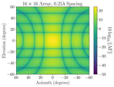
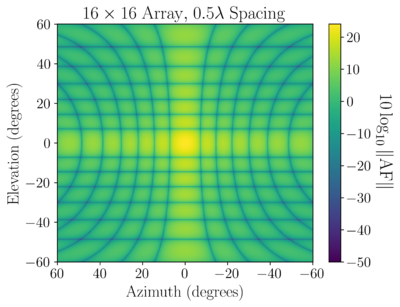
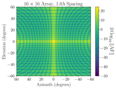
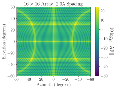
It is common in engineering to provide phased array values in decibels through . Recalling the complex exponential in the array factor equation above, often, what is really meant by array factor is the magnitude of the summed phasor produced at the end of array factor calculation. With this, we can produce the following equation:
This represents a coordinate frame whose axis is aligned with the array axis, and whose axis is aligned with the array axis.
If we consider a phased array, this process provides the following values for , when steering to bore-sight (,):

|

|

|

|
These values have been clipped to have a minimum of -50 dB, however, in reality, null points in the array factor pattern will have values significantly smaller than this.
المنظور والمعادلات الرياضية
الآن ، إضافة مصطلح φ إلى تأثير الهامش في الناتج المدى الثاني:
إن أخذ مربع دالة الموجة يعطينا شدة الموجة.
الآن مساحة الباعثات مسافة جانباً. يتم اختيار هذه المسافة لتبسيط الحساب ولكن يمكن تعديلها على أنها أي جزء عددي من الطول الموجي.
كما يحقق الجيب أقصى حد له , نضع البسط في الجزء الثاني = 1.
وهكذا مع ازدياد حجم "N" ، سيهيمن على المصطلح .بما أن الجيب يمكن أن يتذبذب بين −1 و 1 ، يمكننا أن نرى ذلك الإعداد سوف يرسل الحد الأقصى من الطاقة على زاوية من قبل
الأنواع المختلفة للمصفوفات الطورية
المصفوفة الطورية المتحركة
المصفوفة الطورية الثابتة
المصفوفة الطورية النشطة
المصفوفة الطورية الغير نشطة
انظر أيضاً
- Active electronically scanned array
- Antenna array
- Aperture synthesis
- Beamforming
- Interferometric synthetic-aperture radar
- Inverse synthetic-aperture radar
- Multi-user MIMO
- Optical heterodyne detection
- Phased array ultrasonics
- Phased-array optics
- Radar MASINT
- Side-scan sonar
- Single-frequency network
- Smart antenna
- Synthetic-aperture radar
- Synthetic aperture sonar
- Synthetically thinned aperture radar
- Thinned-array curse
- Wave field synthesis
- History of smart antennas
- Reconfigurable antenna
المصادر
- ^ Milligan, Thomas A. (2005). Modern Antenna Design, 2nd Ed. John Wiley & Sons. ISBN 0471720607.
- ^ أ ب ت Balanis, Constantine A. (2015). Antenna Theory: Analysis and Design, 4th Ed. John Wiley & Sons. pp. 302–303. ISBN 1119178983.
- ^ Stutzman, Warren L.; Thiele, Gary A. (2012). Antenna Theory and Design. John Wiley & Sons. p. 315. ISBN 0470576642.
- ^ Lida, Takashi (2000). Satellite Communications: System and Its Design Technology. IOS Press. ISBN 4274903796.
- ^ Laplante, Phillip A. (1999). Comprehensive Dictionary of Electrical Engineering. Springer Science and Business Media. ISBN 3540648356.
- ^ أ ب Visser, Hubregt J. (2006). Array and Phased Array Antenna Basics. John Wiley & Sons. pp. xi. ISBN 0470871180.
- ^ Golio, Mike; Golio, Janet (2007). RF and Microwave Passive and Active Technologies. CRC Press. p. 10.1. ISBN 142000672X.
- ^ Mazda, Xerxes; Mazda, F. F. (1999). The Focal Illustrated Dictionary of Telecommunications. Taylor & Francis. p. 476. ISBN 0240515447.
- ^ قالب:FS1037C MS188 Definition of Phased Array Archived 2004-10-21 at the Wayback Machine. Accessed 27 April 2006.
- ^ Sturdivant, Rick; Quan, Clifton; Chang, Enson (2018). Systems Engineering of Phased Arrays. Artech House. ISBN 978-1630814885.
- ^ Sturdivant, Rick; Harris, Mike (2015). Transmit Receive Modules for Radar and Communication Systems. Norwood, MA: Artech House. ISBN 978-1608079797.
- ^ Pandey, Anil (2019). Practical Microstrip and Printed Antenna Design (in الإنجليزية). Bostan: Artech House. p. 443. ISBN 9781630816681.
- ^ Braun, Karl Ferdinand (1967) [Delivered 11 December 1909]. "Electrical Oscillations and Wireless Telegraphy". Nobel Lectures, Physics 1901-1921. Amsterdam: Elsevier. Retrieved 29 July 2023 – via nobelprize.org. Braun's Nobel Prize lecture. The phased array section is on pages 239–240.
- ^ "Die Strassburger Versuche über gerichtete drahtlose Telegraphie" (The Strassburg experiments on directed wireless telegraphy), Elektrotechnische und Polytechnische Rundschau (Electrical technology and polytechnic review [a weekly]), (1 November 1905). This article is summarized (in German) in: Adolf Prasch, ed., Die Fortschritte auf dem Gebiete der Drahtlosen Telegraphie [Progress in the field of wireless telegraphy] (Stuttgart, Germany: Ferdinand Enke, 1906), vol. 4, pages 184–185.
- ^ http://www.100jahreradar.de/index.html?/gdr_5_deutschefunkmesstechnikim2wk.html Archived 2007-09-29 at the Wayback Machine Mamut1 first early warning PESA Radar
- ^ W. J. Evanzia. "Faster, lighter 3-D radars in sight for tactical warfare". Electronics. 1966. p. 81, 83, 87.
- ^ "A Fully Integrated 24GHz 8-Path Phased-Array Receiver in Silicon" (PDF). Archived (PDF) from the original on 2018-05-11.
- ^ "A 24GHz Phased-Array Transmitter in 0.18μm CMOS" (PDF). Archived (PDF) from the original on 2018-05-11.
- ^ "A 77GHz 4-Element Phased Array Receiver with On-Chip Dipole Antennas in Silicon" (PDF). Archived (PDF) from the original on 2018-05-11.
- ^ "A 77GHz Phased-Array Transmitter with Local LO- Path Phase-Shifting in Silicon" (PDF). Archived (PDF) from the original on 2015-09-09.
- ^ World’s Most Complex Silicon Phased Array Chip Developed at UC San Diego Archived 2007-12-25 at the Wayback Machine in UCSD News (reviewed 2 November 2007)
- ^ See Joseph Spradley, "A Volumetric Electrically Scanned Two-Dimensional Microwave Antenna Array," IRE National Convention Record, Part I – Antennas and Propagation; Microwaves, New York: The Institute of Radio Engineers, 1958, 204–212.
- ^ "AEGIS Weapon System MK-7". Jane's Information Group. 2001-04-25. Archived from the original on 1 July 2006. Retrieved 10 August 2006..
- ^ Scott, Richard (April 2006). "Singapore Moves to Realise Its Formidable Ambitions". Jane's Navy International. 111 (4): 42–49.
- ^ Corum, Jonathan (April 30, 2015). "Messenger's Collision Course With Mercury". New York Times. Archived from the original on 10 May 2015. Retrieved 10 May 2015.
- ^ Wallis, Robert E.; Cheng, Sheng. "Phased-Array Antenna System for the MESSENGER Deep Space Mission" (PDF). Johns Hopkins University Applied Physics Laboratory. Archived from the original (PDF) on 18 May 2015. Retrieved 11 May 2015.
- ^ National Oceanic and Atmospheric Administration. PAR Backgrounder Archived 2006-05-09 at the Wayback Machine. Accessed 6 April 2006.
- ^ Otsuka, Shigenori; Tuerhong, Gulanbaier; Kikuchi, Ryota; Kitano, Yoshikazu; Taniguchi, Yusuke; Ruiz, Juan Jose; Satoh, Shinsuke; Ushio, Tomoo; Miyoshi, Takemasa (February 2016). "Precipitation Nowcasting with Three-Dimensional Space–Time Extrapolation of Dense and Frequent Phased-Array Weather Radar Observations". Weather and Forecasting. 31 (1): 329–340. Bibcode:2016WtFor..31..329O. doi:10.1175/WAF-D-15-0063.1.
- ^ P. D. Trinh, S. Yegnanarayanan, F. Coppinger and B. Jalali Silicon-on-Insulator (SOI) Phased-Array Wavelength Multi/Demultiplexer with Extremely Low-Polarization Sensitivity Archived 2005-12-08 at the Wayback Machine, IEEE Photonics Technology Letters, Vol. 9, No. 7, July 1997
- ^ "Electronic Two-Dimensional Beam Steering for Integrated Optical Phased Arrays" (PDF). Archived (PDF) from the original on 2017-08-09.
- ^ "An 8x8 Heterodyne Lens-less OPA Camera" (PDF). Archived (PDF) from the original on 2017-07-13.
- ^ "A One-Dimensional Heterodyne Lens-Free OPA Camera" (PDF). Archived (PDF) from the original on 2017-07-22.
- ^ Elon Musk, Mike Suffradini (7 July 2015). ISSRDC 2015 – A Conversation with Elon Musk (2015.7.7) (video). Event occurs at 46:45–50:40. Retrieved 2015-12-30.
- ^ "Mojix Star System" (PDF). Archived from the original (PDF) on 16 May 2011. Retrieved 24 October 2014.
- ^ "Airborne Ultrasound Tactile Display". Archived from the original on 18 March 2009. SIGGRAPH 2008, Airborne Ultrasound Tactile Display
- ^ "Touchable Holography". Archived from the original on 2009-08-31. Retrieved 2009-08-22. SIGGRAPH 2009, Touchable holography
- ^ Hay, S.G.; O’Sullivan, J.D. (2008). "Analysis of common-mode effects in a dual-polarized planar connected-array antenna". Radio Science. 43 (6): RS6S04. Bibcode:2008RaSc...43.6S04H. doi:10.1029/2007RS003798.
- ^ أ ب "Antenna Arrays: A Computational Approach | IEEE eBooks | IEEE Xplore". ieeexplore.ieee.org. Retrieved 2023-05-20.
- ^ أ ب ت Balanis, Constantine A. (2015). Antenna Theory: Analysis and Design, 4th Ed. John Wiley & Sons. ISBN 978-1119178989.
وصلات خارجية
- Radar Research and Development - Phased Array Radar—National Severe Storms Laboratory
- Shipboard Phased Array Radars
- NASA Report: MMICs For Multiple Scanning Beam Antennas for Space Applications
- Principle of Phased Array
- 'Phased Array' microphone system of Tony Faulkner
- Software tool to predict the radiation pattern of an antenna array


![{\displaystyle AF=\sum _{n=1}^{N}I_{n1}\left[\sum _{m=1}^{M}I_{m1}\mathrm {e} ^{j\left(m-1\right)\left(kd_{x}\sin \theta \cos \phi +\beta _{x}\right)}\right]\mathrm {e} ^{j\left(n-1\right)\left(kd_{y}\sin \theta \sin \phi +\beta _{y}\right)}}](https://wikimedia.org/api/rest_v1/media/math/render/svg/4a686704d08fddcf1e4c28e20539128eec275be2)


![{\displaystyle AF_{dB}=10\log _{10}{\Bigg \|}\sum _{n=1}^{N}I_{1n}\left[\sum _{m=1}^{M}I_{m1}\mathrm {e} ^{j\left(m-1\right)\left(kd_{x}\sin \theta \cos \phi +\beta _{x}\right)}\right]\mathrm {e} ^{j\left(n-1\right)\left(kd_{y}\sin \theta \sin \phi +\beta _{y}\right)}{\Bigg \|}}](https://wikimedia.org/api/rest_v1/media/math/render/svg/be5ed8dad8492fa8caa75f70534f27a07263d9b5)


