ناخب (الكترونيات)


الناخب (MULTIPLEXERS) هو عبارة عن جهاز يوجه المعلومات الرقمية المأخوذة من عدة مصادر لنقلها على خط نقل واحد إلى الوجهة المقصودة. حيث له عدة مداخل و خرج وحيد و له أيضاً مداخل تحكم تسمح للبيانات الرقمية الموجودة على أي خط من خطوط الدخل لتفتح على الخرج,ولهذا سميت بمنتخبات البيانات.
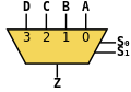
ويبين الشكل التالي ناخباً له أربعة خطوط دخل ومدخلين تحكم لأنه مع اختيار خانتين يمكن اختيار أي خط من أربعة خطوط.
إن تواجد الشيفرة الثنائية على مداخل الناخب A0,A1)) سيمكن البيانات المختارة من على الدخل من المرور إلى الخرج,فإذا تم تطبيق الرقم الثنائي A0=0,A1=0)) على مداخل التحكم فإن بيانات الدخل S0سوف تظهر على الخرج,وإذا تم تطبيق الرقم الثنائيA0=1,A1=0)) فإن بيانات الدخل S1 سوف تظهر على الخرج,وإذا تم تطبيق الرقم الثنائيA0=0,A1=1)) فإن بيانات الدخل S2 ستظهر على الخرج أما إذا تم تطبيق الرقم الثنائيA1=1,A0=1)) على المداخل فسوف تظهر بيانات الدخل S3 على الخرج. إن التعبير المنطقي لخرج الناخب يمكن أن يستنتج كما يلي: • بيانات الخرج تساوي بيانات S0 فقط عندما يكون:A0=0,A1=0 وبالتالي فإن: Y=S0A1¯A0¯ • بيانات الخرج تساوي بيانات S1 فقط عندما يكون:A1=0,A0=1 وبالتالي فإن: Y=S1A1¯A0 • بيانات الخرج تساوي بيانات S2 فقط عندما يكون:A1=1,A0=0 وبالتالي فإن: Y=S2A1A0¯ • بيانات الخرج تساوي بيانات S3 فقط عندما يكون:A1=1,A0=1 وبالتالي فإن: Y=S3A1A0 فيكون التابع الكلي للخرج هو: Y=S0A1¯A0¯+S1A1¯A0+S2A1A0¯+S3A1A0 ويمكن بناء الدارة المنطقية لهذا التابع بواسطة أربع بواباتAND ثلاثية المداخل وبوابة واحدة OR بأربعة مداخل ودارتين NOT لإيجاد متممات A1,A0 وهي دارة الناخب:
. . . . . . . . . . . . . . . . . . . . . . . . . . . . . . . . . . . . . . . . . . . . . . . . . . . . . . . . . . . . . . . . . . . . . . . . . . . . . . . . . . . . . . . . . . . . . . . . . . . . . . . . . . . . . . . . . . . . . . . . . . . . . . . . . . . . . . . . . . . . . . . . . . . . . . . . . . . . . . . . . . . . . . . .
الناخب الرقمي
In digital circuit design, the selector wires are of digital value. In the case of a 2-to-1 multiplexer, a logic value of 0 would connect to the output while a logic value of 1 would connect to the output. In larger multiplexers, the number of selector pins is equal to where is the number of inputs.


For example, 9 to 16 inputs would require no fewer than 4 selector pins and 17 to 32 inputs would require no fewer than 5 selector pins. The binary value expressed on these selector pins determines the selected input pin.
A 2-to-1 multiplexer has a boolean equation where and are the two inputs, is the selector input, and is the output:


Which can be expressed as a truth table:
| 0 | 1 | 1 | 1 |
| 1 | 0 | 1 | |
| 0 | 1 | 0 | |
| 0 | 0 | 0 | |
| 1 | 1 | 1 | 1 |
| 1 | 0 | 0 | |
| 0 | 1 | 1 | |
| 0 | 0 | 0 |
This truth table should make it quite clear that when then but when then . A straightforward realization of this 2-to-1 multiplexer would need 2 AND gates, an OR gate, and a NOT gate.


Larger multiplexers are also common and, as stated above, requires selector pins for inputs. Other common sizes are 4-to-1, 8-to-1, and 16-to-1. Since digital logic uses binary values, powers of 2 are used (4, 8, 16) to maximally control a number of inputs for the given number of selector inputs.
4-to-1 mux
8-to-1 mux

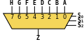
16-to-1 mux


The boolean equation for a 4-to-1 multiplexer is:

Two realizations for creating a 4-to-1 multiplexer are shown below:
| ||||


تسلسل الناخبين
Larger multiplexers can be constructed by using smaller multiplexers by chaining them together. For example, an 8-to-1 multiplexer can be made with two 4-to-1 and one 2-to-1 multiplexers. The two 4-to-1 multiplexer outputs are fed into the 2-to-1 with the selector pins on the 4-to-1's put in parallel giving a total number of selector inputs to 3, which is equivalent to an 8-to-1.
قائمة الدارات المدمجة التي تقوم بالانتخاب
The 7400 series has several ICs that contain multiplexer(s):
| S.No. | IC No. | الوظيفة | Output State |
|---|---|---|---|
| 1 | 74157 | Quad- 2:1 MUX | Output same as input given |
| 2 | 74158 | Quad- 2:1 MUX | Output is inverted input |
| 3 | 74153 | Dual- 4:1 MUX | Output same as input |
| 4 | 74352 | Dual- 4:1 MUX | Output is inverted input |
| 5 | 74151A | 8:1 MUX | Both outputs available ie. Complementary outputs |
| 6 | 74151 | 8:1 MUX | Output is inverted input |
| 7 | 74150 | 16:1 MUX | Output is inverted input |
مواضيع ذات صلة
- الموزعات
- Barrel shifter
- MDM
- Inverse multiplexer
- Statistical multiplexer
- Digital subscriber line access multiplexer (DSLAM)
- Rule 184, a cellular automaton in which each cell acts as a multiplexer for the values from the two adjacent cells
- Multiplexing
المراجع
- مبادئ التصميم الالكتروني و الرقمي د. سليم عمر ادريس.
http://www.ee.surrey.ac.uk/Projects/Labview/multiplexer/index.html