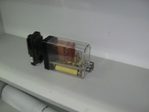
مرحل
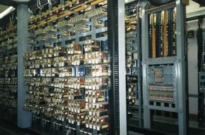
المرحـِّل أو الحاكمة relay، هو مقلاد يعمل بالكهرباء تستخدم الكثير من المراحل الكهرومغناطيسية لتشغيل الآلات آلياً، مع استخدام المبادئي الأساسية الأخرى للتشغيل. تستخدم المراحل عند الحاجة للتحكم في دائرة عن طريق اشارة طاقة منخفضة (مع العزل الكهربائي الكامل بين التحكم ودوائر التحكم)، أو في الدوائر المختلفة التي تتطلب التحكم بإشارة واحدة. كانت المراحل الأولى تستخدم في دوائر البرق على المسافات الطويلة، حيث كانت تقوم بتكرير الإشارة القامة من دائرة واحدة وتعيد نقلها للدائرة التالية. تستخدم المراحل على نطاق واسع في سنترالات الهواتف وفي الحواسب الأولى للقيام بالعمليات المنطقية.
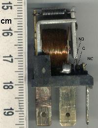
يتكون المرحل من مفتاح ميكانيكي يمكن التحكم به كهربائياً من خلال تطبيق جهد على الملف الموجود بداخلها. هذا العنصر يعتبر عنصراً استطاعياً أكثر من كونه عنصراً إلكترونياً، بالرغم من وجود عناصر تسمى المراحل الصغيرة، تركب على الدراات الإلكترونية، وهو يتوفر بأحجام متعددة واستطاعات مختلفة تبدأ من 1 أمبير حتى 60 أمبير، ولها دور كبير في الدارات الصناعية في حال كوننها يمكن أن تحل محل ناقل الطاقة الذي يصدر أصواتاً عالية عند الفتح والإغلاق.[1]
ومن أكثر استخداماتها في الدارات الإلكترونية، وهو قيادة مرحلة الخرج النهائي من خلال التحكم بالجهد المطبق على ملف المرحل باستخدام ترانزستور صغير لا يتجاوز تياره 1 أمبير.
وتنتشر في التطبيقات الصناعية؛ في دارات المنظمات الكهربائية وأجهزة الحاسوب ودارات المصاعد والأبواب الكهربائية والعديد من التطبيقات الأخرى.
بالإضافة لكونها تتوفر بتيارات متعددة، هي أيضاً تتوفر بجهود تحكم متعددة أيضاً حسب النظم العالمية.
التصميم الأساسي والتشغيل
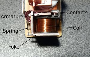
يتكون المرحل من جزئين رئيسيين وهما:
- الملف المغناطيسي: يستخدم المرحل قطعة حديدية ملفوف حوله سلك. فعندما يمر التيار الكهربائي في السلك يتكون مجال مغناطيسي وتتحول القطعة الحديدية إلى مغناطيس.
- المفتاح: ويتخذ وضعان، الوضع الطبيعي غير ملامس، ووضع التوصيل، الملامس. عند مرور التيار الثابت في الملف، يبدأ المغناطيس الكهربائي بالعمل فينجذب الذراع المعدني إلى الأسفل وتكتمل الدائرة فيبدأ التيار في السريان إلى الدائرة.
الأنواع
هناك أنواع مختلفة من المراحل تصنف حسب عدد نقاط التلامس وعدد حوامل التماسات. فعدد حوامل التمامسات يحدد عدد ما يسمى بالاقطاب وعدد نقاط التلامس يحدد ما يسمى بالتحويلات.
المرحل ذو القطب الواحد والتحويلة الواحدة
في هذا المرحل يكون هناك ذراع واحد (أي قطب واحد) وتكون لهذا الذراع نقطة واحدة.
المرحل ذو القطبين والتحويلة الواحدة
في هذا المرحل يوجد هناك ذراعان تتحرآان بنفس الوقت و لكل ذراع نقطة تلامس واحدة.
المرحل ذو القطبين وتحويلتين
في هذا المرحل يكون هناك ذراعان تتحرآان بنفس الوقت ولكن لكل ذراع نقطتي تلامس.
Latching relay
Reed relay
Mercury-wetted relay
Polarized relay
Machine tool relay
Ratchet relay
Coaxial relay
الواصل الكهربائي
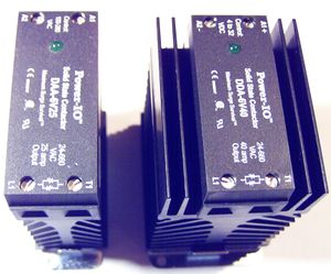
مرحل الحالة الصلبة

المرحل واصل الحالة الصلبة
مرحل بوشلهولز
مراحل التلامس الموجه
مرحال الحماية من الحمل الزائد
التطبيقات
لا يقتصر استخدام المراحل على التطبيقات البسيطة فقط، وإنما تتعدى بكونها عنصراً يستخدم في لوحات التحكم الصناعية آداةٍ لحماية الأحمال الكهربائية من أخطار زيادة تيار التحميل.
تتوافر هذه المراحل بتيارات قياسية متعددة (من 6 حتى 250 أمبير) وتكون قابلة للمعايرة في زمن الفصل عند زيادة تيار الحمل، وتيار الفصل الذي يجيب أن يفصل المرحل عنده بعد انقضاء زمن الفصل.
فمثلاً، في محرك ضاغط لسحب المياه من بئر، استطاعته 10 حصان أي 7360 وواط، يعمل على توتر ثلاثي الطور 380 فولت بتردد 50 هرتز وعم استطاعته 0.87. والمطلوب حماية هذا المحرك من خطر التحميل الزائد للمحرك الذي يمكن أن ينجم إما عن إنخفاض جهد التغذية أو زيادة الحمل على محور المحرك. في هذه الحالة يجب اختيار عنصر المرحل بحيث يكون تيارها قريباً من تيار المحرك مع العلم أن الشركات المصنعة قد أخذت بعين الاعتبار استطاعات المحركات القياسية المصنعة من قبل شركات المحركات.
في العصر الحديث تتواجد مراحل إلكترونية، يمكن معايرتها بدقة كبيرة وتعطي التيارات على الحمل من خلال محولات تسمى بمحولات الشدة وتكون كوسيط بين العنصر والحمل يمر من خلالها سلك التغذية الرئيسي للحمل.
تستخدم المراحل في التطبيقات التالية:
- Amplifying a digital signal, switching a large amount of power with a small operating power. Some special cases are:
- A telegraph relay, repeating a weak signal received at the end of a long wire
- Controlling a high-voltage circuit with a low-voltage signal, as in some types of modems or audio amplifiers,
- Controlling a high-current circuit with a low-current signal, as in the starter solenoid of an automobile,
- Detecting and isolating faults on transmission and distribution lines by opening and closing circuit breakers (protection relays),
- Isolating the controlling circuit from the controlled circuit when the two are at different potentials, for example when controlling a mains-powered device from a low-voltage switch. The latter is often applied to control office lighting as the low voltage wires are easily installed in partitions, which may be often moved as needs change. They may also be controlled by room occupancy detectors to conserve energy,
- Logic functions. For example, the boolean AND function is realised by connecting normally open relay contacts in series, the OR function by connecting normally open contacts in parallel. The change-over or Form C contacts perform the XOR (exclusive or) function. Similar functions for NAND and NOR are accomplished using normally closed contacts. The Ladder programming language is often used for designing relay logic networks.
- The application of Boolean Algebra to relay circuit design was formalized by Claude Shannon in A Symbolic Analysis of Relay and Switching Circuits
- Early computing. Before vacuum tubes and transistors, relays were used as logical elements in digital computers. See electro-mechanical computers such as ARRA (computer), Harvard Mark II, Zuse Z2, and Zuse Z3.
- Safety-critical logic. Because relays are much more resistant than semiconductors to nuclear radiation, they are widely used in safety-critical logic, such as the control panels of radioactive waste-handling machinery.
- Time delay functions. Relays can be modified to delay opening or delay closing a set of contacts. A very short (a fraction of a second) delay would use a copper disk between the armature and moving blade assembly. Current flowing in the disk maintains magnetic field for a short time, lengthening release time. For a slightly longer (up to a minute) delay, a dashpot is used. A dashpot is a piston filled with fluid that is allowed to escape slowly. The time period can be varied by increasing or decreasing the flow rate. For longer time periods, a mechanical clockwork timer is installed.
- Vehicle battery isolation. A 12v relay is often used to isolate any second battery in cars, 4WDs, RVs and boats.
- Switching to a standby power supply.
اعتبارات في تطبيقات المرحل

- Number and type of contacts – normally open, normally closed, (double-throw)
- Contact sequence – "Make before Break" or "Break before Make". For example, the old style telephone exchanges required Make-before-break so that the connection didn't get dropped while dialing the number.
- Rating of contacts – small relays switch a few amperes, large contactors are rated for up to 3000 amperes, alternating or direct current
- Voltage rating of contacts – typical control relays rated 300 VAC or 600 VAC, automotive types to 50 VDC, special high-voltage relays to about 15 000 V
- Operating lifetime, useful life - the number of times the relay can be expected to operate reliably. There is both a mechanical life and a contact life; the contact life is naturally affected by the kind of load being switched.
- Coil voltage – machine-tool relays usually 24 VDC, 120 or 250 VAC, relays for switchgear may have 125 V or 250 VDC coils, "sensitive" relays operate on a few milliamperes
- Coil current - including minimum current required to operate reliably and minimum current to hold. Also effects of power dissipation on coil temperature at various duty cycles.
- Package/enclosure – open, touch-safe, double-voltage for isolation between circuits, explosion proof, outdoor, oil and splash resistant, washable for printed circuit board assembly
- Operating environment - minimum and maximum operating temperatures and other environmental considerations such as effects of humidity and salt
- Assembly – Some relays feature a sticker that keeps the enclosure sealed to allow PCB post soldering cleaning, which is removed once assembly is complete.
- Mounting – sockets, plug board, rail mount, panel mount, through-panel mount, enclosure for mounting on walls or equipment
- Switching time – where high speed is required
- "Dry" contacts – when switching very low level signals, special contact materials may be needed such as gold-plated contacts
- Contact protection – suppress arcing in very inductive circuits
- Coil protection – suppress the surge voltage produced when switching the coil current
- Isolation between coil contacts
- Aerospace or radiation-resistant testing, special quality assurance
- Expected mechanical loads due to acceleration – some relays used in aerospace applications are designed to function in shock loads of 50 g or more
- Accessories such as timers, auxiliary contacts, pilot lamps, test buttons
- Regulatory approvals
- Stray magnetic linkage between coils of adjacent relays on a printed circuit board.
There are many considerations involved in the correct selection of a control relay for a particular application. These considerations include factors such as speed of operation, sensitivity, and hysteresis. Although typical control relays operate in the 5 ms to 20 ms range, relays with switching speeds as fast as 100 us are available. Reed relays which are actuated by low currents and switch fast are suitable for controlling small currents.
As for any switch, the current through the relay contacts (unrelated to the current through the coil) must not exceed a certain value to avoid damage. In the particular case of high-inductance circuits such as motors other issues must be addressed. When a power source is connected to an inductance, an input surge current which may be several times larger than the steady current exists. When the circuit is broken, the current cannot change instantaneously, which creates a potentially damaging spark across the separating contacts.
Consequently for relays which may be used to control inductive loads we must specify the maximum current that may flow through the relay contacts when it actuates, the make rating; the continuous rating; and the break rating. The make rating may be several times larger than the continuous rating, which is itself larger than the break rating.
Derating factors
| Type of load | % of rated value |
|---|---|
| Resistive | 75 |
| Inductive | 35 |
| Motor | 20 |
| Filament | 10 |
| Capacitive | 75 |
Undesired arcing
Protective relays
Railway signalling
التاريخ
انظر أيضاً
- Contactor
- Digital protective relay
- Dry contact
- Race condition
- Stepping switch - a kind of multi-position relay
- Wire spring relay
المصادر
- Gurevich, Vladimir (2005). Electrical Relays: Principles and Applications. London - New York: CRC Press.
- Westinghouse Corporation (1976). Applied Protective Relaying. Westinghouse Corporation. Library of Congress card no. 76-8060.
- Terrell Croft and Wilford Summers (ed) (1987). American Electricians' Handbook, Eleventh Edition. New York: McGraw Hill. ISBN 978-0-07-013932-9.
{{cite book}}:|author=has generic name (help) - Walter A. Elmore. Protective Relaying Theory and Applications. Marcel Dekker kana, Inc. ISBN 978-0-8247-9152-0.
- Vladimir Gurevich (2008). Electronic Devices on Discrete Components for Industrial and Power Engineering. London - New York: CRC Press. p. 418.
- Vladimir Gurevich (2003). Protection Devices and Systems for High-Voltage Applications. London - New York: CRC Press. p. 292.
- Vladimir Gurevich (2010). Digital Protective Relays: Problems and Solutions. London - New York: CRC Press. p. 422.
- Colin Simpson, Principles of Electronics, Prentice-Hall, 2002, ISBN 0-06-868603-6 قالب:Please check ISBN
